DIY Arduino Oscilloscope with the Nokia 3310 GLCD screen

I’ve seen videos on YouTube using an Arduino and a Graphical LCD screen (GLCD) to create a simple Oscilloscope. The annoying thing is that I found no help whatsoever on how to build one. I spent a few days figuring out how to use the Nokia 3310 LCD screen and then figuring out how to sample an analog port to create a fun oscilloscope effect.

I don’t claim that this device can replace actual test equipment but it might be useful and for $40.00 bucks in total parts it is a blast to play with.

image

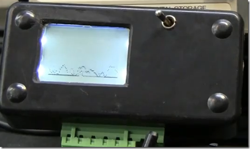
The setup is really simple, connect an Arduino Pro Mini to a Nokia 3310 LCD screen, sample an analog port and then wright the pixels to the screen. I even added two potentiometers, one that adds delay to the sample to essentially provide a basic time scale and another pot that can scale down voltages as long as they are below three volts (the operating voltage of the micro controller). Unfortunately if you want to sample sign waves that have voltages over three volts you are out of luck unless you build an electronic circuit to scale it down somehow.

Another unfortunate feature is that the analog input only shows positive voltage so the scope is really a positive DC or AC scope only. Here again custom electronics could be built but there is something beautiful about keeping it simple.

image

I don’t have a professional function generator so I could only test its range from 100 ms to about 1 ms scales.

Bottom line, it is definitely fun to build and play with, it also makes a cool EMF detector


Related posts:

Arduino 6 AI temperature scanner with LCD display

Arduino Arrays and Recursion Tutorial

DIY Function (Signal) Generator


Supporting files:

Sketch and library:Arduino Oscilloscope

Schematic:Arduino Oscilloscope

Here is the Sketch

/* 
###########################################################
  Title:       Arduino Oscilloscope
  Purpose:     Use a Nokia 3310 GLCD screen with the arduino
  Created by:  Fileark. see Fileark.com for more info.
  Note:        Please reuse, repurpose, and redistribute this code.
  Note:        This code uses the Adafruit PDC8544 LCD library  
###########################################################
 */

#include "PCD8544.h"

// pin 3 - Serial clock out (SCLK)
// pin 4 - Serial data out (DIN)
// pin 5 - Data/Command select (D/C)
// pin 7 - LCD chip select (CS)
// pin 6 - LCD reset (RST)
PCD8544 nokia = PCD8544(3, 4, 5, 7, 6);

// a bitmap of a 16x16 fruit icon
static unsigned char __attribute__ ((progmem)) logo16_glcd_bmp[]={
0x06, 0x0D, 0x29, 0x22, 0x66, 0x24, 0x00, 0x01, 0x87, 0x00, 0x27, 0x6C, 0x20, 0x23, 0x06, 0x00,
0x00, 0x00, 0x00, 0x00, 0x00, 0x10, 0x10, 0x00, 0x03, 0x00, 0x00, 0x00, 0x00, 0x00, 0x00, 0x00, };
#define LOGO16_GLCD_HEIGHT 16 
#define LOGO16_GLCD_WIDTH  16 

int channelAI = A0;      // select the input pin for the Oscilioscope
int scaleYAI = A1;       // select the input pin for the Y (horizontal) potentiometer
int scaleXAI = A2;       // select the input pin for the X (Vertical) potentiometer

int delayVariable = 0;   // define a variable for the Y scale / delay
int xVariable = 0;       // define a variable for the x scale 
int yCtr = 0;            // define a variable for the y counter used to collect y position into array
int posy = 0;            // define a variable for the y position of the dot 
int myArray[85];         // define an array to hold the data coming in 


void setup(void) 
{

  nokia.init();
  
  // turn all the pixels on (a handy test)
    nokia.command(PCD8544_DISPLAYCONTROL | PCD8544_DISPLAYALLON);
    delay(500);
  // back to normal
    nokia.command(PCD8544_DISPLAYCONTROL | PCD8544_DISPLAYNORMAL);
  
  // show splashscreen
    nokia.display();
    delay(500);
    nokia.clear();
}

void loop() 
{  
  delayVariable = analogRead(scaleYAI);
  delayVariable = (delayVariable/50);
  xVariable = analogRead(scaleXAI);
  xVariable = (xVariable/22); 
  
  for(yCtr = 0; yCtr < 85; yCtr += 1)   // the for loop runs from 0 and < 85, it fills the array with 84 records
    {                                 
      posy = analogRead(channelAI);       // read the value from the sensor:
      myArray[yCtr] = (posy/xVariable);   // scale the value based on the x scale potentiometer      
      delay (delayVariable);           // scale the y collection of data using the delay from the y potentiometer   
    }
  
  yCtr == 0;                           // set the counter to zero so we can use it again
  nokia.clear();                       // clear the LCD screen so we can draw new pixels
 
  for(yCtr = 0; yCtr < 85; yCtr += 1)  // for loop runs 84 times
    {
       nokia.setPixel(yCtr, myArray[yCtr], BLACK); // draw the 84 pixels on the screen
    }
  
  nokia.display();                     // show the changes to the buffer
  yCtr == 0;                           // set the counter to zero so we can use it again
     
} 


5 thoughts on “DIY Arduino Oscilloscope with the Nokia 3310 GLCD screen”

  1. very nice!
    thanks for posting code and schematics!

    have you thought about or tried grabbing the signal sample in the atmegas isr loop?
    should give you faster and thus more acurate sampling!

    correct me if i’m wrong!

    cheers,
    peek

    • Thanks Peek, I have no idea what you are talking about so no, I have not thought of that lol. I look forward to anyone that takes interest and refines or comes up with a better method! (I am not a pro just someone learning) I have other hardware lying around that I wanted to try too for the learning experience, Netduino, Stellaris LM3S811, hopefully I get the time to do that.

  2. well, i’m no pro too, newbie tinkerer.
    i just recently got into sound stuff with arduino and the timer interrupts play an important role there.

    this post explains how sampling with arduino works best:
    http://interface.khm.de/index.php/lab/experiments/arduino-realtime-audio-processing/

    beware: cryptic assembler stuff in the example codes!
    (i myself don’t understand most of the stuff going on there ;))

    but for starters, maybe you can speed up sampling by just disabling the timers like in this example:
    http://jeelabs.org/2010/11/23/100-khz-dso/
    seems easy to do!

    if i get a display and find some time, i’ll give it a try.

  3. kann das Sketch nicht fehlerfrei übersetzen. Der Fehler ist in “PCD8544.h”… PCD8544(int8_t SCLK, int8_t DIN, int8_t DC, int8_t CS, int8_t RST) : _din(DIN), _sclk(SCLK), _dc(DC), _rst(RST), _cs(CS) {}

    Vielen Dank für Ihre Hilfe

Leave a Comment