Arduino Electronic Speed Control ESC 2 of 2

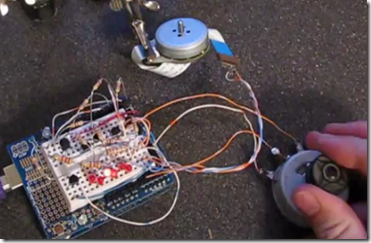
Here is my second ESC or Electronic Speed Control that I built with an Arduino Duemilanove. You can’t just hook DC up to Brushless DC Motors that you have scavenged out of old CDROM drives, hard drives, or printers and expect them to spin.  Brushless DC motors require you to use a motor controller to produce a three phase DC square wave.

image

This project is just like my last ESC circuit but I have added a potentiometer for speed control. For more detailed information check out the last ESC post and video as well.Here are the project files including schematic and sketch.

PDF’s:Arduino ESC2.0

ZIP:ArduinoESC2.0


Here is the Arduino sketch.

——————————————————————

/*
 
Brushless DC Motor Control ESC 2.0
 
This sketch cascades 6 outputs which when connected properly
 can generate a three phase square wave which can in turn run
 a brushless DC motor.
 
This circuit has advanced from my Brushless DC Motor Control
 ESC 1.0 because I have added a speed control potentiometer
 to control the motor speed.
 
I suggest that you not try to run a motor directly off of the outputs
 of the Arduino but use some transistors to handle the load.
 
For the schematic and supporting documents for this project go to
 
http://filear.com
 
Made by Fileark. 2010-0826
 
*/
 // Here we are declaring six variables called led 1 through led6
 // We are also assigning the variables to the physical discrete pins
 // Outputs can be any outputs you want
 int led1 =  0;
 int led2 =  1;
 int led3 =  2;
 int led4 =  3;
 int led5 =  4;
 int led6 =  5;
 int potpin = 0;  //This is the analog input for the pot
 int val;         //This is the val varible for the speed
 
// The setup() method runs once, when the sketch starts
 
void setup()   {
 // initialize the digital pin as an output:
 pinMode(led1, OUTPUT);
 pinMode(led2, OUTPUT);
 pinMode(led3, OUTPUT);
 pinMode(led4, OUTPUT);
 pinMode(led5, OUTPUT);
 pinMode(led6, OUTPUT);
 }
 
// the loop() method runs over and over again,
 // as long as the Arduino has power
 /*
 LESD1, LED3, and LED5 will be positive, LED2, LED4, and LED6 are negative.
 You will notice that two LEDs are on at the same time so that one of the
 three motor coils are energised at a time.
 */
 void loop()
 {
 val = analogRead(potpin);   // reads the pot and assigns the value to “val”
 digitalWrite(led5, LOW);    // set the fifth LED off
 digitalWrite(led1, HIGH);   // set the first LED on
 delay(val);                 // wait for a period of time
 digitalWrite(led6, LOW);    // set the sixth LED off
 digitalWrite(led2, HIGH);   // set the second LED on
 delay(val);                 // wait for a period of time
 digitalWrite(led1, LOW);    //repeat ect.
 digitalWrite(led3, HIGH);
 delay(val);
 digitalWrite(led2, LOW);
 digitalWrite(led4, HIGH);
 delay(val);
 digitalWrite(led3, LOW);
 digitalWrite(led5, HIGH);
 delay(val);
 digitalWrite(led4, LOW);
 digitalWrite(led6, HIGH);
 delay(val);
 }


Leave a Comment