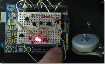
Here is my first ESC or Electronic Speed Control that I built with an Arduino Duemilanove. If you don’t already know, the best motors you can scavenge out ov CDROM drives or old hard drives are Brushless DC motors that you can’t just hook DC up to and make it spin. Brushless DC motors require you to use a motor controller to produce a three phase DC square wave. Brushless DC motors are almost identical in nature to three phase AC motors. As you can imaging it is not that easy to create a three phase square wave and I couldn’t find any really good easy examples online so here you go. If you are interested in building your own download the schematic, sketch, and some PDFs I found with good information all zipped up here.
PDFs: Arduino ESC1.0
ZIP: ArduinoESC1.0

Before you start let me say that the Arduino can not handle the current necessary to turn the motor so transistors are required to keep the Atmega chip from smoking. Also, as a safety precaution I usually use something like 1K resistors coming off of the outputs of the Arduino to help protect the board from short circuit.
You can purchase a retail ESC for RC hobby motors (RC planes, boats, and cars) for anywhere from $10.00 to $200.00 depending on the quality and amperage rating. I doubt that a home made ESC will come even close to the quality of a commercial product but it is fun to try.
Here is the Arduino sketch.
________________________________________________
2 thoughts on “Arduino Electronic Speed Control ESC 1 of 2”
Hello,
Thanks for this great tutorial!
I was able to improve on your Arduino sketch to achieve higher RPM. The only change I made was using delayMircoseconds() which gives more accurate control over the transition between phases. Also I added in a “warm up” routine which gradually gets the motor up to speed.
I made a video of it: http://www.youtube.com/watch?v=2CTxh-TckQk
And here is the modified sketch:
/*
Brushless DC Motor Control ESC 1.0
This sketch cascades 6 outputs which when connected properly
can generate a three phase square wave which can in turn run
a brushless DC motor.
I suggest that you not try to run a motor directly off of the outputs
of the Arduino but use some transistors to handle the load.
For the schematic and supporting documents for this project go to
http://filear.com
Made by Fileark. 2010-0826
Modified by enygmatronics(youtube) 2013-06-21
*/
// Here we are declaring six variables called led 1 through led6
// We are also assigning the variables to the physical discrete pins
// Outputs can be any outputs you want
int led1 = 0;
int led2 = 1;
int led3 = 2;
int led4 = 3;
int led5 = 4;
int led6 = 5;
boolean warmUp = true;
// The setup() method runs once, when the sketch starts
void setup() {
// initialize the digital pins as outputs
pinMode(led1, OUTPUT);
pinMode(led2, OUTPUT);
pinMode(led3, OUTPUT);
pinMode(led4, OUTPUT);
pinMode(led5, OUTPUT);
pinMode(led6, OUTPUT);
}
// the loop() method runs over and over again,
// as long as the Arduino has power
/*
LESD1, LED3, and LED5 will be positive, LED2, LED4, and LED6 are negative.
You will notice that two LEDs are on at the same time so that one of the
three motor coils are energised at a time.
*/
void loop()
{
if (warmUp) {
for (int i=20; i>0; i--) {
pulseCoilsMicro(10000);
}
for (int i=20; i>0; i--) {
pulseCoilsMicro(9000);
}
for (int i=20; i>0; i--) {
pulseCoilsMicro(8000);
}
for (int i=20; i>0; i--) {
pulseCoilsMicro(7500);
}
for (int i=20; i>0; i--) {
pulseCoilsMicro(7000);
}
for (int i=20; i>0; i--) {
pulseCoilsMicro(6500);
}
for (int i=20; i>0; i--) {
pulseCoilsMicro(6000);
}
for (int i=20; i>0; i--) {
pulseCoilsMicro(5500);
}
for (int i=20; i>0; i--) {
pulseCoilsMicro(5000);
}
for (int i=20; i>0; i--) {
pulseCoilsMicro(4500);
}
for (int i=20; i>0; i--) {
pulseCoilsMicro(4000);
}
for (int i=20; i>0; i--) {
pulseCoilsMicro(3500);
}
for (int i=20; i>0; i--) {
pulseCoilsMicro(3100);
}
for (int i=20; i>0; i--) {
pulseCoilsMicro(3000);
}
for (int i=20; i>0; i--) {
pulseCoilsMicro(2900);
}
for (int i=20; i>0; i--) {
pulseCoilsMicro(2800);
}
for (int i=40; i>0; i--) {
pulseCoilsMicro(2750);
}
for (int i=40; i>0; i--) {
pulseCoilsMicro(2700);
}
for (int i=40; i>0; i--) {
pulseCoilsMicro(2650);
}
for (int i=40; i>0; i--) {
pulseCoilsMicro(2600);
}
for (int i=40; i>0; i--) {
pulseCoilsMicro(2550);
}
for (int i=40; i>0; i--) {
pulseCoilsMicro(2500);
}
for (int i=40; i>0; i--) {
pulseCoilsMicro(2450);
}
for (int i=40; i>0; i--) {
pulseCoilsMicro(2400);
}
for (int i=40; i>0; i--) {
pulseCoilsMicro(2350);
}
}
warmUp = false;
pulseCoilsMicro(2300);
}
void pulseCoilsMicro(int delayMicroSeconds) {
digitalWrite(led5, LOW); // set the fifth LED off
digitalWrite(led1, HIGH); // set the first LED on
delayMicroseconds(delayMicroSeconds); // wait for a period of time
digitalWrite(led6, LOW); // set the sixth LED off
digitalWrite(led2, HIGH); // set the second LED on
delayMicroseconds(delayMicroSeconds); // wait for a period of time
digitalWrite(led1, LOW); //repeat ect.
digitalWrite(led3, HIGH);
delayMicroseconds(delayMicroSeconds);
digitalWrite(led2, LOW);
digitalWrite(led4, HIGH);
delayMicroseconds(delayMicroSeconds);
digitalWrite(led3, LOW);
digitalWrite(led5, HIGH);
delayMicroseconds(delayMicroSeconds);
digitalWrite(led4, LOW);
digitalWrite(led6, HIGH);
delayMicroseconds(delayMicroSeconds);
}
void pulseCoilsMilli(int delayMilliSeconds) {
digitalWrite(led5, LOW); // set the fifth LED off
digitalWrite(led1, HIGH); // set the first LED on
delay(delayMilliSeconds); // wait for a period of time
digitalWrite(led6, LOW); // set the sixth LED off
digitalWrite(led2, HIGH); // set the second LED on
delay(delayMilliSeconds); // wait for a period of time
digitalWrite(led1, LOW); //repeat ect.
digitalWrite(led3, HIGH);
delay(delayMilliSeconds);
digitalWrite(led2, LOW);
digitalWrite(led4, HIGH);
delay(delayMilliSeconds);
digitalWrite(led3, LOW);
digitalWrite(led5, HIGH);
delay(delayMilliSeconds);
digitalWrite(led4, LOW);
digitalWrite(led6, HIGH);
delay(delayMilliSeconds);
}
hi!
thanks to both of you!
I am working ni a project, and it looks that you could help me, and also be interested in have some fun trying to make it work…!
I want to make and esc (could be arduino based), with a special feature…
I want to control a sensored bldc motor without any potentionemer or any kind of input device… let me explain myself… imagine a motor conected to a wheel, and as you fisicaly move the wheel, the sensors in the motor will determinate the speed that the motor is spining (let’s say that the speed is calculated after 1-2 seconds of manual spinning) and automaticly set this speed as the desired speed to be mantain… so the esc starts to work…
the ideal would be that just giving one simple push to the wheel this esc will detect the maximum speed and mantain it.
Do you imagine how to make this possible?
I am using a rc sensored bldc motor, that works with 7.4 volts,
http://www.hobbyking.com/hobbyking/store/uh_viewItem.asp?idProduct=17743
is really easy to get the signals from it’s sensors, and they are super precise…
tell me something!
thanks!